Logic gate circuit drawer Logic level converter van 3.3 naar 12 v How to make resistor transistor logic gates custom ma
Decoder logic circuit diagram and operation - Electronic Clinic
What is emitter coupled logic (ecl) circuit?
Level shifter circuit diagram
Logic gate (page 1) / science hq / math is fun forumLogic directional mosfet Electrical symbols, electrical diagram symbolsWhat is logic diagram and truth table?.
Solved problems on cmos logic circuitsBi-directional logic level converter using mosfet Logic gates circuitsLogic gates circuits.

Logic gates circuit types circuits integrated scale large various
Circuit simplification examplesPriority encoder Logic converter sparkfun iemand bewerkstelligenLogic diagram gates table truth circuit circuits excel gcse computer science computerscience.
Decoder logic circuit diagram and operationCombinational logic circuits using logic gates Preparing a logic pro session for notationPseudo nmos logic.

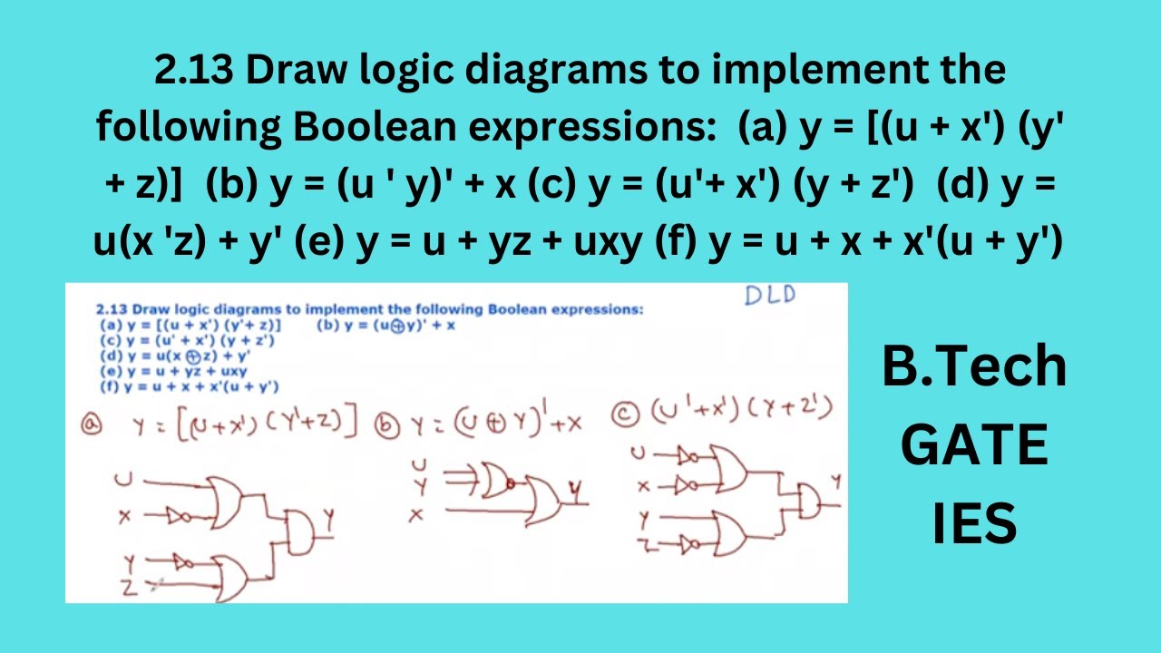
2.13 draw logic diagram to implement the following boolean expressions
Solved: '3) the logic circuit shown in the diagram directly implementsBasic comparator operations with circuit diagram examples Decoder logic circuit diagram and operationLogic combinational gates circuits using gate boolean algebra electronics circuit combination example three electrical full nand below these operators shown.
Full adderLogic gates truth table and diagram Logic gate symbols diagram electrical diagrams elements wiring engineering draw library conceptdraw schematic drawing alu pic boolean examples bit templateDecoder logic circuit diagram and operation.

What are logic gates?
Given the boolean function (zx+y') (xy+z') 1.obtain the truth table ofWhat is generic array logic (gal)? – circuit reset Circuit simplification examples boolean gate circuits simplify semiconductor expression digital write algebra electronicsHow to create a logic gate diagram.
74f245d-74f245-sop20-logic-circuit.jpgGive the logic circuit diagram of the expression: ((xy)’ + (x+y)’)’ Logic truthLogic adder example2.

Logic level converter
.
.